Sextant Use in Space
Topic outline
-
Sextant Use for Position in Space
Version 1: July 2023
Contributor: Peter HIggins, Ph.D.
Keywords: sextant, astronomy, navigation, celestial sphere, declination, right ascension, topodetic coordinates, limb, star atlas, sightings
Appropriate for: 9-12 grades
Prerequisites required: None
Prerequisites helpful: algebra I, geometry
Intended lesson duration: 1 week
Student expectation: Learn to use a sextant, and how sextants are used in navigation. Learn coordinate systems describing positions on Earth and in space.
Table of Contents
History of Sextant Navigation. 4
Sextant use in Gemini, Skylab, Apollo and the International Space Station. 7
International Space Station, ISS.. 10
Assemble a Cardboard Sextant from a kit 13
Buy a Sextant Ready to use. 13
Build a Sextant, the Simple NASA Sextant 13
Build a Sextant, A4 Sextant 14
Making or acquiring the mirror 14
Hands-on Making Observations. 16
Measurement of Latitude using Polaris. 16
Measurement of Latitude by a noon solar sighting – an example. 17
Making the solar noon sighting. 17
Data analysis using Nautical Almanac. 18
Angular coordinates on the Earth’s surface. 21
Using a sextant for navigation on the Moon or Mars. 23
Exploration far from base station. 23
Understanding coordinates in Space. 24
-
The reason students interested in space and space travel should learn about sextant navigation is that the sextant has proven to be valuable for establishing spacecraft position in emergencies.
If power to instruments is lost, and communications to ground controllers interrupted, it becomes highly desirable for the crew to be able to determine their position and velocity. This information is needed for maintaining, or altering, spacecraft trajectory.
Sailors have done this by themselves for thousands of years by observing the Sun and stars, and since the 18th century they have used an instrument called a sextant for this task. Based on successful astronaut testing on manned flights, NASA has investigated favorably using emergency sextant positioning for their future missions to meet its need for astronaut autonomous navigation[1]
Another reason for learning to use a sextant is the value of using instruments for making and accurately recording measurements in the process of becoming a scientist. Richard Feynman wrote:
The principle of science, the definition, almost, is the following: The test of all knowledge is experiment. Experiment is the sole judge of scientific ‘truth’.
(Feynman, Leighton and Sands 1963, p. 1-1)Youtube.com hosts many tutorials on how to use a sextant for navigation, for example: Taking Sights With a Sextant – Sextant Tutorial #3.
-
Objective of this section
Summarize how navigation with instruments developed, and what measurements were made with them.
Early History[1]
The early history of navigation over vast bodies of water highlights sailing in the Mediterranean and the northern and southern Pacific Ocean. In the North Pacific it began with sailers from Taiwan spreading Southwards between 3000 and 1000 BC. Starting about 900 BC the Polynesians explored the Southern Pacific. The Polynesians used navigation tools, but also bird observation, waves and swells.
Until the 18th century, the conventional method of navigating was based on latitude only. For example, sailors would determine the latitude of the home port by means discussed next. They would sail away and return to the home port by sailing north or south until they reached the home port’s latitude then turn east or west maintaining this latitude until home. They knew they were east or west by dead reckoning.
The determination of latitude was straightforward and known to be the altitude of the Sun as it crosses the zenith local meridian. This was measured by several angle measuring devises beginning with the very simple kamal and the cross staff, progressing to the quadrant and eventually the sextant. The kamal was a small card or bone having a knotted cord passed through its center. One end was held in the teeth, the other stretched out to length by an arm. The card was moved outward with the bottom marking the horizon until the top just occult’s the star observed, such as Polaris, The knots recorded how far the card moved from which its altitude is determined. The cross staff is a stick with a moving transom calibrated in degrees. The observer moves the transom until it lines up with the target star.
The quadrant
The quadrant shown in Figure 1 was an important angle measuring instrument preceding the sextant that was used by the Greeks. The height of stars was measured by observing where a weighted hanging cord crossed the scale of the graduated arc while sighting the star along the upper edge. Note that the NASA simple sextant (Figure 6) is actually a quadrant.
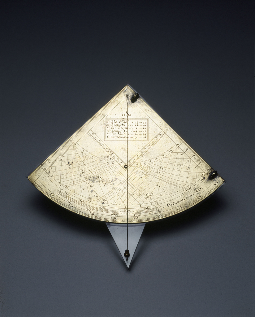
Figure 1 An ancient quadrant (Jeanne Willox-Egnor, The Mariners Museum,
http://www.mariner.org/exhibitions/highlights/scientific_quadrant.php)
Lunar Distance
Historically, the determination of longitude had been difficult to do. Before the invention of the gimballed ship’s chronometer in the 18th century by John Harrison[2] (1730) which could accurately extend Greenwich time to any ship position, sailer’s used the method of lunar distance. Figure 2 illustrates how this method worked.
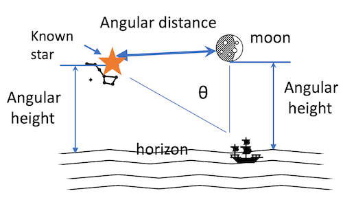
Figure 2 Lunar Distance
In this method three measurements were made by an angle measuring device (later by sextant):
1. the angular height of a reference star
2. the angular height of the moon or of a planet close to the reference star
3. the least angular distance between the reference star and the moon or planet
With these measurements, tables were consulted to yield local time for these observables. From this time the longitude was determined.
[1] Peter Ifland, The History of the Sextant, Science Museum of the University of Coimbra, Oct 3, 2000
[2] See Longitude found – The Story of Harrison’s Clocks, Royal Museums Greenwich www. rmg.co.uk
-
Objective of this section
Document the use of sextants on NASA missions, what experiments were done with them, astronaut training and their performance.
NASA sextant experience
Some form of sextant, both marine classical, and one specially designed and built by NASA Ames, has been used in all prior NASA missions and in NASA simulators. Sextant objectives were:
Overview
In the Gemini XII mission, a sextant was used to support calculation of the time and direction of Gemini spacecraft thruster burns required to dock it with the companion Agena vehicle. The Skylab TOO-2 experiments on SL/2 and SL/3 probed the accuracy of sextant observations for safe interplanetary manual navigation.[1] During the dramatic Apollo 13 malfunction a sextant was employed by Lovell to measure the coordinates of the terminator line on Earth (the arc on Earth between daylight and darkness) to facilitate the final reentry maneuver that provided a safe return to Earth. A sextant has been used extensively on the International Space Station for star sightings which allow calculation of spacecraft position, course and speed.
Gemini
The Gemini Summary Conference Report[2] tells us that subsequent to Gemini VI-A, to be able to respond to Inertial Measuring Unit failure, a hand held sextant was provided for determining time of arrival at terminal-phase initiation.
Gemini XII
Due to problems with the onboard radar, a sextant attached to a special bracket, was used by crew member Buzz Aldrin[3] to allow calculation of the time and direction of Gemini spacecraft thruster burns required to dock it with the companion Agena vehicle. Otherwise sextant experiments were included in the flight plan. In particular an Ames report[4] lists the objectives and results of the sextant experiment conducted by Aldrin to determine the effect of the actual space-flight envi ronment on the navigator performance. The results show that:
“(1) hand-held sextant measurement performance is excellent providing a standard deviation of measurement error less than 10 arc seconds; (2) spacecraft rotational motion and the actual spacecraft environment had little effect on the navigator performance; and ( 3 ) window-induced measurement errors i n the Gemini XI1 spacecraft were small and predictable. The optical hand-held sextant appears to have application to on-board navigation for future manned space flights.”
Apollo 8
A sextant was integrated into the Apollo Guidance System that was operated by crew member James Lovell.
Early in the Apollo program, NASA contracted with the MIT Instrumentation Laboratory in Cambridge, Massachusetts for a space sextant to be incorporated into Apollo’s guidance and navigation system.
The sextant fulfilled the need for a device to aid the alignment and to bound the drift of the spacecraft’s inertial guidance system. It consisted of two telescopes. The first was a one-power, wide-field scanning telescope, which was used to locate a star or constellation in space. The second was a 28-power sextant, for the actual reading. It didn’t look like a marine sextant, but it operated like one. As planned, an astronaut sighted on two heavenly bodies: two stars, or a star and the horizon of the Earth or Moon, then made adjustments until they were aligned over one another. Pressing a button stored the instrument reading and time to allow the on-board Apollo Guidance Computer (AGC) to compute the spacecraft’s position, based on those readings.
The Apollo 8 mission, in December 1968, provided a real test of this device especially since this mission was first to engage the crew in navigating across the depths of space from one heavenly body to another.
By 1968, however, the on-board system had evolved from being the primary navigation system to being the back-up to a ground-based navigation system. In the initial planning stages for Apollo, this extensive use of ground facilities was not foreseen. It was speculated that the Soviet Union, whom the Americans were racing to the Moon, might jam the signals from Earth. However, the Deep Space Network was completed in 1961 comprising three 85-foot parabolic dish antennas placed approximately 120 degrees apart on the Earth which added the capability of precisely tracking the Apollo spacecraft from the ground.
James Lovell, a navy officer, was the primary navigator for the mission. But, as the spacecraft left Earth orbit, Lovell found it difficult to get precise readings because of small particles that surrounded the Command Module and because they never were in absolute darkness. Establishing the Earth’s limb was difficult due to the atmosphere, but they found that correcting for gyroscopic drift was relatively easy. Lovell would key in the code for a star into the computer, and the computer in turn would rotate the spacecraft until that star appeared in the telescope’s cross-hairs. The extent to which a star was off-center indicated the amount of drift. The astronaut would manipulate the optics until the star was centered, then press a button, and the computer would realign the gyros.
By the second day, Lovell was making much more precise readings. Despite having an extremely limited memory compared to modern computers, the Apollo Guidance Computer was able to take Lovell’s readings and translate them into accurate position and velocity data.
With the position and velocity computed on-board agreeing closely with what was computed on the ground, the astronauts had confidence that they would safely pass by the Moon but not impact it. This was a genuine concern, as mission plans called for them to establish an orbit only 60 nautical miles above the Moon’s far side, where they would not be in radio contact with anyone on Earth. If their calculations were off by even a few percent, they would have been on a course to impact the far side of the Moon, with ground controllers unable to help them. The system performed equally well on the return journey, controlling the burn that took the astronauts out of lunar orbit on a trajectory back to Earth, aligning the Command Module to a precise angle to enter the Earth’s atmosphere, and bringing the crew down to a safe splashdown in the Pacific.
Apollo 13
The Apollo 8 mission played a central role for the use of a sextant in space. As it happened, this experience with sextant use would be a lifesaver on bringing the crippled Apollo 13 spacecraft safely back home. When normal spacecraft guidance was lost (see the movie Apollo 13 for this dramatic story) it fell on its commander, the same Jim Lovell who on Apollo 8 had learned to use the sextant for backup navigation, to align the spacecraft for a critical re-entry course correction. Normally, he would do this with star sightings, but the oxygen tank explosion had surrounded his spacecraft with particles and debris to an extent that star sighting was impossible. It was then that an engineer in Houston had a brilliant idea of sighting on the Earth’s terminator line delimitating day and night whose position permitted a computer program to pinpoint Apollo 13’s position. This had to be incredibly accurate, but Lovell did it. See the site https://www.universetoday.com/62763/13-things-that-saved-apollo-13-part-6-navigating-by-earths-terminator/ for this story.
SkyLab[5]
Astronaut observations with a sextant were performed in 22 sessions on mission SL/3 and in 19 sessions during mission SL/4.
Their mission performance was similar to their preflight observations showing no evidence of degradation due to a long term mission.
It was learned that to maintain the required accuracy for interplanetary navigation, the spacecraft window had to be of good optical quality. Additionally, the sextant, methods and procedures needed modification to fulfill mission requirements.
Sextant changes to the device used on Gemini XII included mounting a dial thermometer, removal of the event timing switch and its connector, and modification of the battery compartment and battery change procedure.
It’s interesting to mention that windows on spacecraft can offer significant challenges for sextant viewing. On the ISS the viewing station window consists of 1 inch thick glass, a pressurized 1 inch space then another 1 inch glass. Considering this, it’s significant that acceptable observations were made through it.
The abstract concludes:
An analysis of navigation data collected using a hand-held space sextant on the second and third manned Skylab missions is presented From performance data and astronaut comments it was determined that (l)the space sextant, the sighting station, and the sighting techniques require modification, (2) the sighting window must be of good optical quality, (3) astronaut performance was stable over long mission time, and (4) sightings made with a hand-held sextant were accurate and precise enough for reliable interplanetary manual navigation.
International Space Station, ISS
According to NASA statement in AAS 19-064 by Greg Holt and Brandon Wood ISS astronauts tested a Celestaire Astra III Professional hand-held sextant to demonstrate this sextant's suitability for future manned space missions such as the Artemis mission to the moon. An objective of the sextant experiments conducted June through December 2018 was to develop emergency navigational methods for future flights, to determine an experiment procedure for using the sextant and to do data analysis to identify astronaut error and suitability for navigation corrections.
Report (AAS 19-064) discusses selection criteria and crew training for a flight qualified sextant. Preflight experiments were conducted in a JSC flight simulator with training limited to a hands-on demonstration. Star fields were projected onto a dome for several sessions of star sightings that were done by two crew members. Observations were made by adjustment of the moveable sextant arm as shown in Figure 3
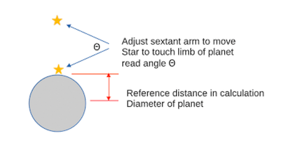
Figure 3 Sextant arm adjustment for ISS star sightings
This angular displacement was read from the main sextant scale and refined from the vernier scale (A vernier scale subdivides an interval on the main scale into tenths).
The accuracy of repeated observations by two ISS crew members is plotted in Figure 4 which shows their measurements achieved the goal of an accuracy of 60 arc seconds even with window distortion and refraction, and with minimal crew training.
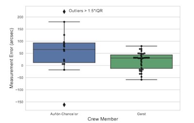
Figure 4 Plot of Astronaut sextant accuracy (NASA report AAS 19-064)
Planned use on Artemis[6]
Perhaps still relying on a sextant in an emergency, Artemis is going to use a star tracker.
In general spacecraft star trackers use cameras to scan the surrounding star field then software compares these images of the star field with an onboard library like that contained in the Cambridge Star Atlas. Typically, this stored star library contains over 3000 stars with their locations dependent on time and seasons. Based on difference analysis between the camera images and the library data on where stars should be for the corrected spacecraft orientation, commands are generated to correct spacecraft position.
NASA plans to return to the moon with the Artemis mission to be launched November 2024 in the new Orion spacecraft. The Orion Spacecraft will use a star tracker and star cameras for orientation and positioning.
The Guidance, Navigation and Control system onboard Orion determines spacecraft position, orientation, and trajectory, and it will command the propulsion system in the service module to maintain course. This device relies on spacecraft sensors to perform these tasks that include a star tracker (Figure 5) and several cameras. The star tracker locks on a star then controls spacecraft thrusters to track the star thus maintaining spacecraft position. The cameras take images of the surrounding star field so that computers can compare these images with stored star fields from a star atlas such as the Cambridge Atlas.
Another camera that will guide Orion is the Optical Navigation, or OpNav, camera which takes images of the Moon and Earth. Based on analysis of these images, the OpNav camera can determine Orion’s angle and its distance from them to keep Orion on course. The camera also can help Orion autonomously return home if the spacecraft were to lose communication with Earth.
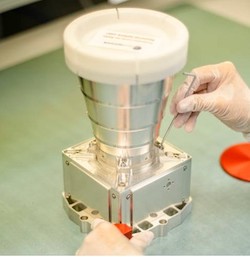
Figure 5 Startracker planned for Orion Spacecraft (NASA picture)
[1] Robert J Randle, NASA TN D=8141; Results of Skylab Experiment T00-2,Manual Navigation Sightings, Ames Research Center, February 1976
[2] Gemini Summary Conference Report, NASA SP 138
[3] Aldrin earned a PhD in astronautics at the Massachusetts Institute of Technology
[4] [4] D.W. Smith, B.A. Lampkin; SEXTANT SIGHTING MEASUREMENTS FROM ON BOARD THE GEMINI XI1 SPACECRAFT; Ames Research Center; 1968
[5] NASA TH D-8141
[6] IEEE Spectrum; 28 August 2022
-
Objective of this section
A sextant should be purchased or built as described in this section so that the class gets hands-on experience with them.
Assemble a Cardboard Sextant from a kit
A sextant kit is available from several companies for under $30. It comes with eyepiece, mirrors and sunshades and requires minimal assembly as pictured in Figure 6.
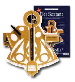
Figure 6 (Google product image from Astroshop.de)
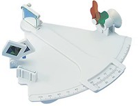
Figure 7 (Amazon product image, Marine Sextant Davis)
Buy a Sextant Ready to use
An inexpensive assembled sextant for classroom study is a Davis Mark 3 starting around $60. As shown in Figure 7.
Build a Sextant, the Simple NASA Sextant
A simple sextant is described by NASA in its publication Build a Simple Sextant available online. This device is pictured in figure 8.
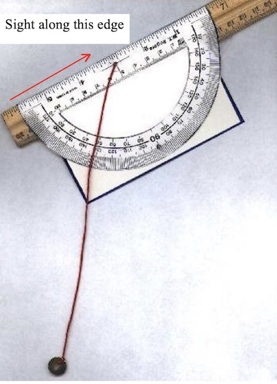
Figure 8 NASA Simple Sextant (NASA mage)
It is made by adding a small weight sufficient to stretch the string straight, such as a large washer, to an end of a 50 cm long string, then attaching the other end to the exact midpoint of a plastic compass by tape or drilling a hole for it. When the straight compass edge is horizontal the string should align with 90 degrees on the compass arc. Horizontal can also be established by a bubble level. The weighted string is equivalent to a plumb bob that hangs vertically due to gravity. This establishes the horizon for the apparatus. Next attach the compass to a ruler more than 40 cm long so that the long edge of the compass is exactly aligned with the edge of the ruler. This can be done with double sided tape. The purpose of the ruler is to extent the straight edge of the compass to make a sighting line, so any straight object will do for this. The white card background helps in reading the compass scale.
Build a Sextant, A4 Sextant
See DIY A4 Sextant on youtube.com for a detailed explanation of how to do this.
Download the sextant face from https://cepe.com.br/nav/A4Sextant/A4SextantHighRes.png and print it on heavy stock white paper at 600 dots per inch. Then proceed as shown in the video.
Making or acquiring the mirror
It’s been my experience as a teacher that many businesses like glass and mirror stores will give teachers supplies from their scrap. I expect this will produce the small mirrors needed for this project, even the half-silvered ones. However, teachers may have to use glass cutters to trim the scrap to the required 4 by 2 cm size. But, in the case donors cannot be found the mirrors can be made
There are several choices for small mirrors when making a sextant as described above. For plain sheet mirrors any glass shop, Home Depot or Lowes sell small sheets for a few dollars which can be cut with a glass cutter into 2 by 4 cm mirrors. For a half-silvered can transparency. Mirrors can be mounted as desired glued to small blocks
3D Print a Sextant
3D printing is an amazing new technology that produces objects from artificial limbs to small public houses by printing them in layers from resins or powders using CAD software. A website explaining the types of 3D printers and what they can produce is https://builtin.com/3d-printing.
The website https://www.thingiverse.com/thing:355337 offers the 3D printer files for a working sextant shown in Figure 9.
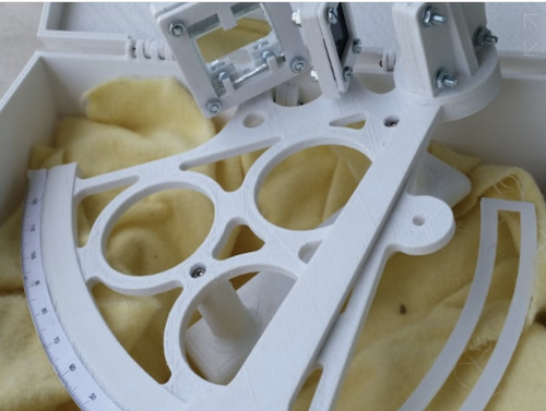
Figure 9 3D printed sextant (credit the sextant project by caltadaniel, June 06, 2014).
The completed plastic sextant made from resins is assembled from 7 printed parts shown below as Figure 10.

Figure 10 (3D printed sextant parts (from the sextant project website https://www.thingiverse.com/thing:355337 )3D
-
Objective of this section
Hands-on measurements are made to determine latitude using a Polaris sighting and an example is given for solar sightings.
Measurement of Latitude using Polaris
A Polaris sighting can be done with either the simple NASA sextant, the A4 built sextant or the purchased one. If you are using the simple NASA sextant the angle is read on the compass where the hanging string crosses the inner scale.
Observations should de done by two students, one to sight on the target, the other to read the scales at the position of the sextant arm for the altitude angle, or the height in degrees, of Polaris above the horizon. Your latitude is simply 90° - (90°-angle read from the sextant scales.. Figure 11 shows why based on two propositions from Euclidean geometry: The sum of the interior angles of a triangle equal 180°, and when two lines cross the opposite angles are equal.
Define the orange triangle with its base line on the Earth’s equator and its hypotenuse by a line from the center of Earth to your location.
1. From geometry the sum of the interior three angles is 180°.
2. Construct a tangent line to your location point. This is your horizon.
3. Θ is the angle to Polaris read from the sextant scale.
Because of right angles the orange interior angle at your location is 90°- Θ°. Exercise for the student – prove this.
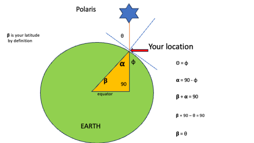
Figure 11 Latitude Angle Proof
Measurement of Latitude by a noon solar sighting – an example
This example illustrates how a sextant is used by a mariner to navigate.
Suppose you are sailing from a marina near North Carolina across the Atlantic Ocean to Bermuda and you want to navigate with a sextant instead of depending on a GPS receiver to continuously determine sailing direction. Figure 12 describes this voyage. The route is from N32 W79 to N32 W64.
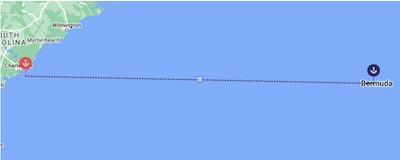
Figure 12 Imagined voyage for sextant trials
Most sailors will use sextant observations to correct the process of dead reckoning. Dead Reckoning is done daily by taking the starting coordinates (the marina on the first day) and plotting that day’s sailing progress based on each compass heading steered by the helmsman, and the vessel’s speed based on the onboard velocity meter or based on logging measurements. The purpose of the sextant measurements is to correct the daily starting coordinates. If the Sun is used for the sightings, then dead reckoning will begin at noon. Two measurements are repeated: latitude and longitude. It is common practice to use solar sightings these. Two things are needed: a sextant and a book of tables known as the Nautical Almanac (freely downloaded).
Making the solar noon sighting
For terrestrial navigation sextant sightings are usually done of the Sun's height around local noon. In Figure 13, the height in degrees between the Sun and the Earth’s horizon is being determined. The Sun image path is indicated by the orange dotted path, and the horizon by the blue dotted path, The sextant arm is adjusted until the lower edge, or limb, of the sun is aligned to just touching the horizon as shown in the figure’s inset.
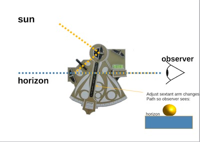
Figure 13 Optical path of sextant sighting
The angle, Θ, read from the index scale must be corrected before calculating latitude or longitude. These corrections include:
1. For height of eye above horizon
2. For index scale not zero when referencing same image
3. For refraction effects which bend light rays near horizon
These corrections are enumerated in the Nautical Almanac.
Data analysis using Nautical Almanac
The procedure for determining your latitude proceeds in steps.
1. Look up the solar (prime) meridian pass in Greenwich Mean Time, GMT, in the daily pages of the Nautical Almanac. Then, using your assumed longitude from dead reckoning, obtain the GMT of your local noon at this longitude. Suppose you estimate your current longitude as W79 °. Dividing by 15° per hour (Earth’s rotation) gives 5:16. If the lookup meridian crossing time is 12:02 at Greenwich (time of noon), the time of noon at your assumed longitude will be 12:02 + 5:16 or 17:18 LGMT.
2. Again using the daily pages, find the sun’s declination at 17 GMT which is N23°.
3. Now compute how high the Sun will be at your assumed latitude of N32°. Subtracting 32° from 90° (your zenith) gives 58° which is the height of the celestial equator relative to your zenith. Since the lookup in step 2 (in hours and minutes) was 23° 26’ north of the celestial equator we add 23° 26’ to 58° telling us that the Sun will pass overhead at our noon at a height of 81°26’.
4. Finally measure the Sun’s actual height with the sextant in small time steps before and after, plot the height of the Sun vs time and interpolate to find the maximum (corrected) value. Suppose this is 81°10’ giving a difference of 16’. Since 1’ of arc is 1 nautical mile and since 81°10’ is less than 81°26’ your actual position is 16 nm further north of your estimate of 32°.
Data used in this section is from a Nautical Almanac. A free Nautical Almanac can be downloaded in various formats from https://www.nauticalalmanac.it/en/pd-eng-nau-alm.
Data on meridian crossing is given in the middle column by date as shown in this page extract from the downloaded atlas, Figure 14.
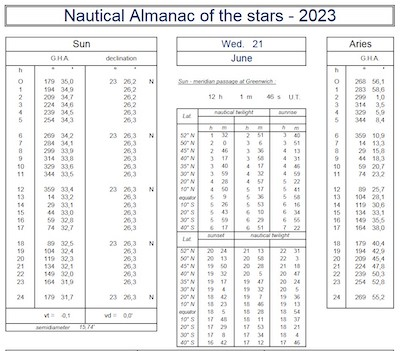
Figure 14 Daily data on meridian crossing
Conversion of degrees to time is also given in the Nautical Almanac.
The procedure for determining your longitude is like the above latitude determination. The objective is determining the GMT time of high noon at your location which is done by making observations every few minutes as the sun approaches and crosses your meridian while recording your GMT time. You have already found that the GMT of noon at the prime meridian to be 12:02. When you plot your observations (height vs local GMT) interpolate the data curve to find the GMT of the highest point which is your noon, now subtract 12:02. This is your longitude hour angle. Convert this to degrees for your longitude. -
Objective of this section
This section explains the use of the coordinate’s latitude and longitude as a means for locating a point on the Earth’s surface, and the relationship between time and longitude.
Angular coordinates on the Earth’s surface
The latitude and longitude determinations detailed so far have been Earth measurements projected on a latitude longitude grid.
Latitude and longitude are an imaginary means for locating a point on earth just as city limits identify a town or the state line describes your state. Neither exist but we behave as if they do when we announce them on signs and include them in maps. Latitude at your location is the intersection of a plane, parallel to the equator, with the surface of the Earth there. This latitude is designated by the angle it makes with the equator at the center of the Earth, as drawn in Figure 15.
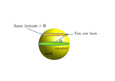
Figure 15 Latitude geometry
If the angle is positive, we label it as North. Latitude tells as where the place is relative to the equator but not which country it's in. To do that another coordinate is needed that is perpendicular to latitude, called longitude, which is a great circle formed by a plane through the center of earth and through the place being marked. Where the 0 reference of latitude is the equator, the 0 reference of longitude is the Greenwich Observatory in Greenwich England. Any place West of there is labeled in degrees with the letter W, any place East uses the letter E.
Universal Time
After the mid-19th century train travel and communications began unifying communities necessitating standardization of time. This happened when a clock called the Shepherd gate clock was installed at the Royal Observatory in Greenwich in August 1852 which was set to local time called Greenwich Mean Time. It is a mean time because solar time varies during the year, so mean is the average of solar time. The time shown on this clock was broadcasted hourly to the World by the British Broadcasting Company, BBC[1]. The significance of this to us is that it is the time at the location of Prime Meridian, i.e., the 0 reference of longitude. This is the time that mariners aboard ships would set their chronometers to.
Your local GMT is the current GMT at Greenwich corrected for the time difference between your location and Greenwich based on the correction time difference:
Your longitude/15°/hr.
[1] Since 1912 GMT time has been broadcasted by radio station WWV located in Ft Collins operated by NIST, U.S. National Institute of Standards and Technology
-
Objective of this section
Using a sextant for planetary surface navigation when compasses won’t work because navigational magnetic fields are not present, and where GPS signals are not available.
Exploration far from base station
Once a base station has been established on the Artemis return to the moon, or on Mars, astronauts will begin exploration of territory around it. Exploring nearby requires no navigation other than tracking by local recognizable references. But exploration far from the base requires some location information, consider the possibilities:
maps: difficult to use because the existing ones are made from high altitude and have no ground perspective. It is noted that Mars was mapped extensively by the Mars Global Surveyor probe that produced beautiful high altitude maps as seen on page 329 of reference 8.
compass: no, the moon has no magnetic field, it’s too small and its core won’t support one. The Martian northern hemisphere is unmagnetized, but the southern hemisphere has areas of strong surface magnification, but Mars has no global magnetic field as was discovered by NASA’s Mars Global Surveyor. T
GPS: no, but - The Earth’s GPS signal received on the moon is 1000 times weaker than on the Earth rendering GPS use there not possible now, and not possible at all on Mars. However, both NASA and the ESA (European Space Agency) are working to extend Earth’s GPS there.
Sextant: yes both on the moon and on Mars. The same training as using it in the spacecraft is sufficient for using it for surface navigation.
-
Objective of this section
This section’s objective is the presentation of the coordinate systems used by NASA for spacecraft guidance and by astronomers for positions of stars.
NASA coordinates in space
There are many coordinate Systems. We start by learning how NASA locates objects in space using a coordinate system called topodetic. In this system position is described by azimuth, elevation and distance (range) as illustrated in Figures 16 a,b,c.
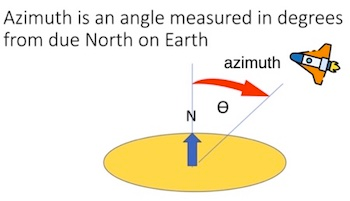
Figure 16 a
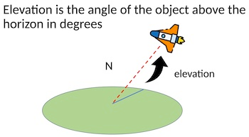
Figure 16b
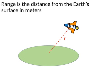
Figure 16c
Figure 16 c
Range (distance) is determined by antennas of the Deep Space Network (DSN) https://en.wikipedia.org/wiki/NASA_Deep_Space_Network that bounce radio signals from the object in space.
Mathematical transformations can be employed to map the azimuth, elevation and range from the Earth’s surface into an inertial coordinate system with an origin at the center of mass of the solar system. It is an inertial coordinate system that is used to control firing of rocket engines and thrusters to propel spacecraft on planned trajectories. Simply stated an inertial coordinate system is one in which particle motion is predicted by Newton’s Laws of Motion.
Celestial Coordinates
Another important coordinate system that should be learned is the one used by astronomers to describe the angular position of stars. Since Greek astronomy stars have been envisioned as embedded in a gigantic sphere surrounding Earth at its center and indefinitely far away. The poles and equator of this sphere are extensions of the spin axis of Earth and the equator of Earth as drawn in Figure 17
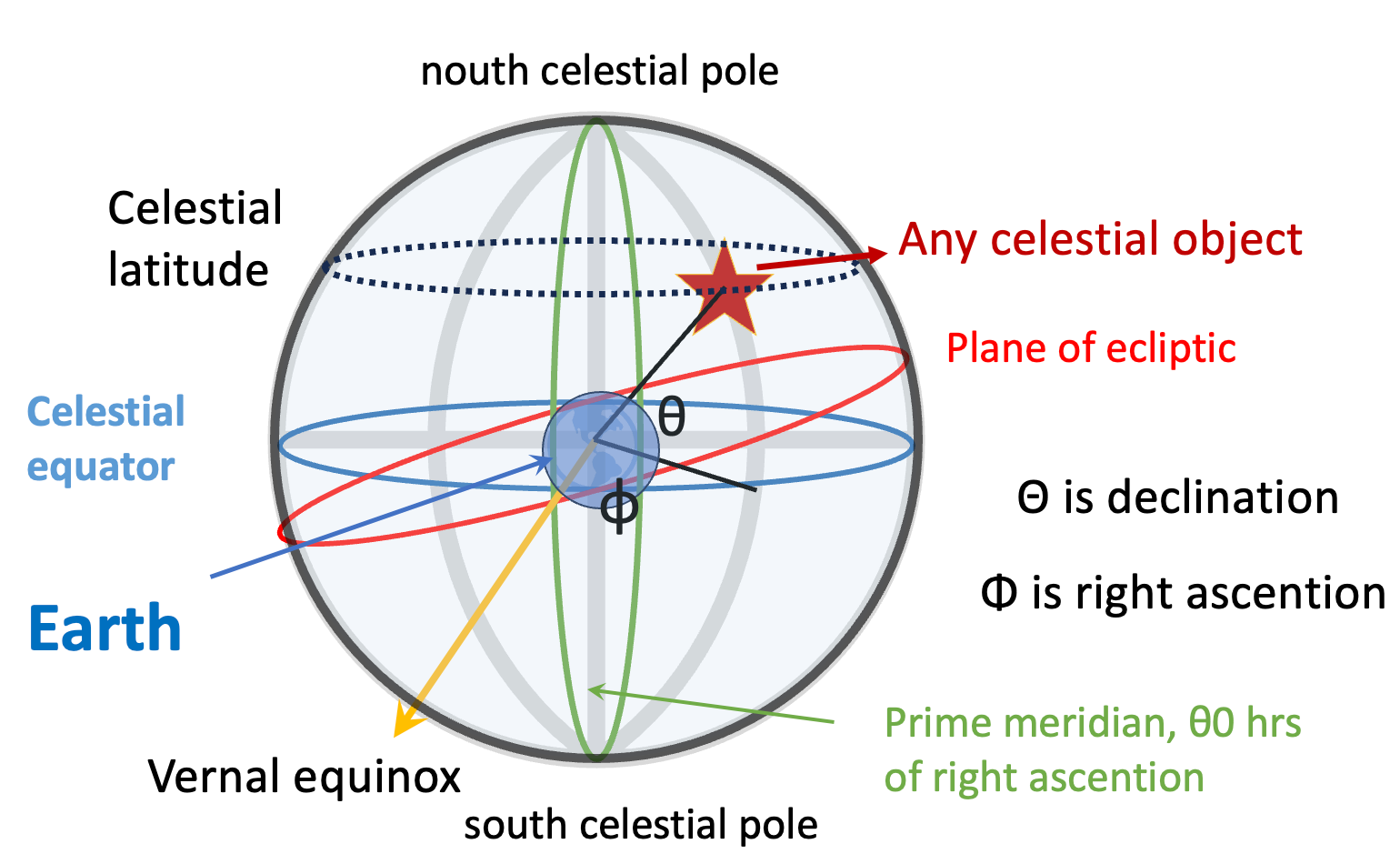
Figure 17 The Celestial Sphere
In this system the azimuth angle in degrees of the topodedic system is replaced with right ascension in hrs:mm:ss whose starting point is the location where the plane of planet motion around the sun crosses Earth’s equator from south to north, a point named the vernal equinox. The declination angle of the celestial system is the same as elevation in the topodedic system. There is no range as the diameter of the celestial sphere is undetermined. The grid of the celestial sphere is the orthogonal parallels of latitude 0-90° and great circles of meridians 0-180 °E and 0-180 °W. The North pole of the celestial sphere coincides almost exactly to the star Polaris. Polaris is easily located in the night sky since it marks the end of the handle of the stellar feature known as the little dipper in the constellation Ursa Minor.
-
Objective of this section
The idea of a student debate is presented in terms of a proposition and arguments for and against.
The debate
It would be a good exercise in learning the material in this lesson for the class to divide and debate the following proposition:
Proposition:
Future manned space missions should include a manual hand-held sextant for navigation in the event that powered navigation systems are inoperative and that external navigation support is unavailable.
Debaters should determine their own arguments, the following are examples:
Arguments for:
1. use of sextants on previous space missions have established efficacy. This fact is established by this document, and NASA has reached this conclusion.
2. experience of Apollo 13 where sextant use was critical for a safe return. This is also true and is well documented.
3. human ingenuity is an important factor in risky pioneering adventures (assumed)
Arguments against:
a. under the stress of emergency, astronauts make mistakes, (documented) For example, it is claimed that on the way back from the Moon on Apollo 8, Jim Lovell reset the guidance system[1] to virtually place the spacecraft back on the launch pad at the Kennedy Space Center. Apollo 8 was on its trans-earth coast, so they had plenty of time to fix this mistake, so it was not an issue.
b. past performance casts some doubt on required accuracy (Figure 5.5 raises questions since the error bars are comparable to the required accuracy of 60 arc seconds plus debris field in an emergency can obscure good sightings). Further, windows must be of very good quality, but could be damaged by long-term exposure to micro-meteorites.
c. progress on sensor automation (James Webb telescope), and advanced star trackers, makes production of a completely automated sextant seem a possibility and a better choice. A battery powered fully automated sextant that can recognize star fields, and using its memory of nautical almanac tables, proceed to automatically calculate latitude and longitude should be possible and would be more reliable.
-
The planned use of sextants for future space travel links future space explorations to sea adventures in our past such as Columbus’ voyages to America or Cook’s discoveries in the Pacific up to Alaska. This lesson restates the role people play in these adventures especially in the example of getting home using ingenuity and a sextant as was the case of Apollo 13. While the focus in the lesson is navigation during space transit, it also probably will apply to traveling great distances across the Moon or Mars if, or when, colonisation occurs.
The lesson includes a central topic of astronomy: The geometry of space described by the celestial sphere. To understand how to use a sextant it’s necessary to learn the coordinates of space. A creditable free online astronomy text, downloadable as pdf, will be an aid in teaching this part, see reference 1.
Learning to take readings from a sextant teaches a fundamental skill needed to be a scientist which is using instruments to make measurements. Nothing is better than hands on experience with a device and repetitive observations to improve accuracy, to analyse results with formulas such as these, https://thenauticalalmanac.com/Formulas.html#Noon_sight-_Determine_Latitude, and to learn how to visualize results with graphics. Teachers are urged to purchase a student sextant, or to oversee building one, and to involve their willing students to learn its use as described in the lesson. There are many on-line nautical almanacs such as referenced in the lesson or http://www.nauticalalmanac.net/pdf/almanac2023.pdf. For the most senior dedicated students this process can become a project involving the application of python code to solve formulas (perhaps by iteration) and to plot results.
In the lesson students learn that NASA missions are scripted by Flight Plans, that flight crews can improvise and maintain composure under pressure, and that astronauts must learn to use instruments. That a sextant was used to bring the crippled Apollo 13 safely home is a great object teaching example.
-
Sextant
A sextant is a hand-held device used to measure the angle in degrees between two objects.
Celestial Sphere
An imaginary sphere of which the observer is the center and on which all celestial objects are considered to lie.
Topodetic Coordinates
Coordinate system used by NASA, using azimuth, elevation and radial distance.
Spacecraft Trajectory
The path that an object with mass in motion follows through space as a function of time, in this case the path a spacecraft follows.
Latitude
The angular distance of a place/celestial object north or south of the earth or celestial equator, usually expressed in degrees and minutes.
Longitude
The angular distance of a place east of west of the meridian at Greenwich, England, or west of the standard meridian of a celestial object, usually expressed in degrees and minutes
Altitude
The apparent height of a celestial object above the horizon, measured as an angle.
Zenith Local Meridian
The plane which passes through the north and south compass points, as well as the zenith.
Zenith Angle
The angle between the sun’s rays and the vertical direction.
Essentially, a continuous portion of a circle, the arc of a sextant in which graduations from zero read in a direction opposite to that of main graduations.
Chronometer
An instrument for measuring time, first developed for marine navigation, being used with astronomical observation to determine longitude.
Greenwich MeanTime
The yearly average of the time each day when the sun crosses the Prime Meridian at the Royal Observatory Greenwich.
Euclidean Geometry
The study of geometrical shapes and figures based on different axioms and theorems.
Inertial Coordinate System
A reference frame formed by assigning coordinates to specific observable objects.
Right Ascension
The distance of a point east of the first point of aries, measured along the celestial equator and expressed in hours, minutes, and seconds.
Declination
The angular distance of a point north or south of the celestial equator.
Ecliptic
A great circle on the celestial sphere representing the sun’s apparent path during the year.
Celestial Body
Objects in space such as the sun, moon, planets, and stars.
Dead Reckoning
The process of calculating one's position, especially at sea, by estimating the direction and distance rather than by using landmarks, astronomical observations, or electronic navigation method
Interpolate
In math, to estimate the value of something given certain data; Generally, to introduce something additional or extraneous between other things or part.
Distortion/Refraction
The act of twisting or altering something out of it true or original state / change in direction of propagation of any wave as a result of its traveling at different speeds at different points along the wave front.
-
1. Astronomy 2e-2e, Open Text Library
2. Ancient Astronomy,James Evans, Oxford University Press, New York 1998 University of Cambridge, New York, NY
3. One Day Celestial Navigation, Otis S Brown, C and O Research, GreenBelt, Maryland
4. Feynman, Leighton, Sands, Lectures on Physics, Addison Wesley
5. Tirion, Wil; The Cambridge Star Atlas; 2nd Edition; Cambridge University Press; 1996
References 6-15 were cited in NASA report AAS 19-064 by Holt and Wood and give an excellent review of sextant use in space.
6. K. Nordtvedt, “A Theory of Manual Space Navigation,” NASA CR-841, Montana State University,March 1967.
7. C. Havill, “An Emergency Midcourse Navigation Procedure for a Space Vehicle Returning From the Moon,” NASA TN-D-1765, NASA Ames Research Center, March 1963.
8. R. Zanetti, “Autonomous Midcourse Navigation for Lunar Return,” Journal of Spacecraft and Rockets,Vol. 44, July-August 2009, pp. 865–873.
9. B. A. Lampkin and R. J. Randle, “Investigation of a Manual Sextant-Sighting Task in the Ames Mid-course Navigation and Guidance Simulator,” Tech. Rep. NASA TN D-2844, NASA Ames ResearchCenter, May 1965.
10. D. W. Smith, “Hand-Held Sextant: Results from Gemini XII and Flight Simulator Experiments,” J.Spacecraft, Vol. 5, June 1968, pp. 655–662.
11. R. H. Battin, Astronautical Guidance. McGraw-Hill, Inc., 1964.
12. P. J. Brennan and I. S. Johnson, “Manually-Aided On-Board Apollo Cislunar Navigation,” Proceedings of the Twenty-Fight Anniversary Year Meeting, Colorado Springs, CO, Institute of Navigation, July 1970.
13. T. M. Eneev, V. V. Ivashkina, V. A. Sharov, and J. V. Bagdasarya, “Space autonomous navigation systemof Soviet project for manned fly by Moon,” Astra Astronautica, Vol. 66, 2009, pp. 341–347.
14. B. Wood and G. Holt, “Orion Sextant Performance Testing and Analysis,” FltDyn-CEV-15-42, NASA Johnson Space Center, September 2015.
15. J. Tukey, Exploratory Data Analysis. Addison-Wesley, 1977.15
-
-
-
-
-
-
-
-